
This "little" tutorial will go through the process of creating fins and fin shapes using curves and surfaces in Maya. I found this method to be the most "accurate"while building out the spiny shapes of fins in my current project, and thought I'd share my process. The tutorial below is broken down into three parts and will cover the basics of working with Curves in Maya.
- A. Building the Main Shape
- B. Creating the Spines
- C. Lofting Fin Shapes
I will be diving into detail about certain tools in Maya. In this tutorial, I will go over using Live surfaces, converting edges to curves, lofting surfaces, converting nurbs to polygons, extrusions and moving constraints like snap to curve and snap to vertex.
A. Building The Main Shape.
Create a base curve .The base curve should match the center line of your mesh. This will define where the fin shape will start. If you have a mesh that is already topologized with a clean center line, extracting a curve from a polygon edge might be the best route. If your mesh is a bit asymmetrical however ( much like my seahorse) drawing a curve along the surface might be the better way to go.
I. Making the base with Polygon Edges to Curve
- 1.) Using Edge Selection, highlight the edge in your geometry you wish to extract. Think about how long across the body, you want your fin to be, and make the edge selection approximately that length.
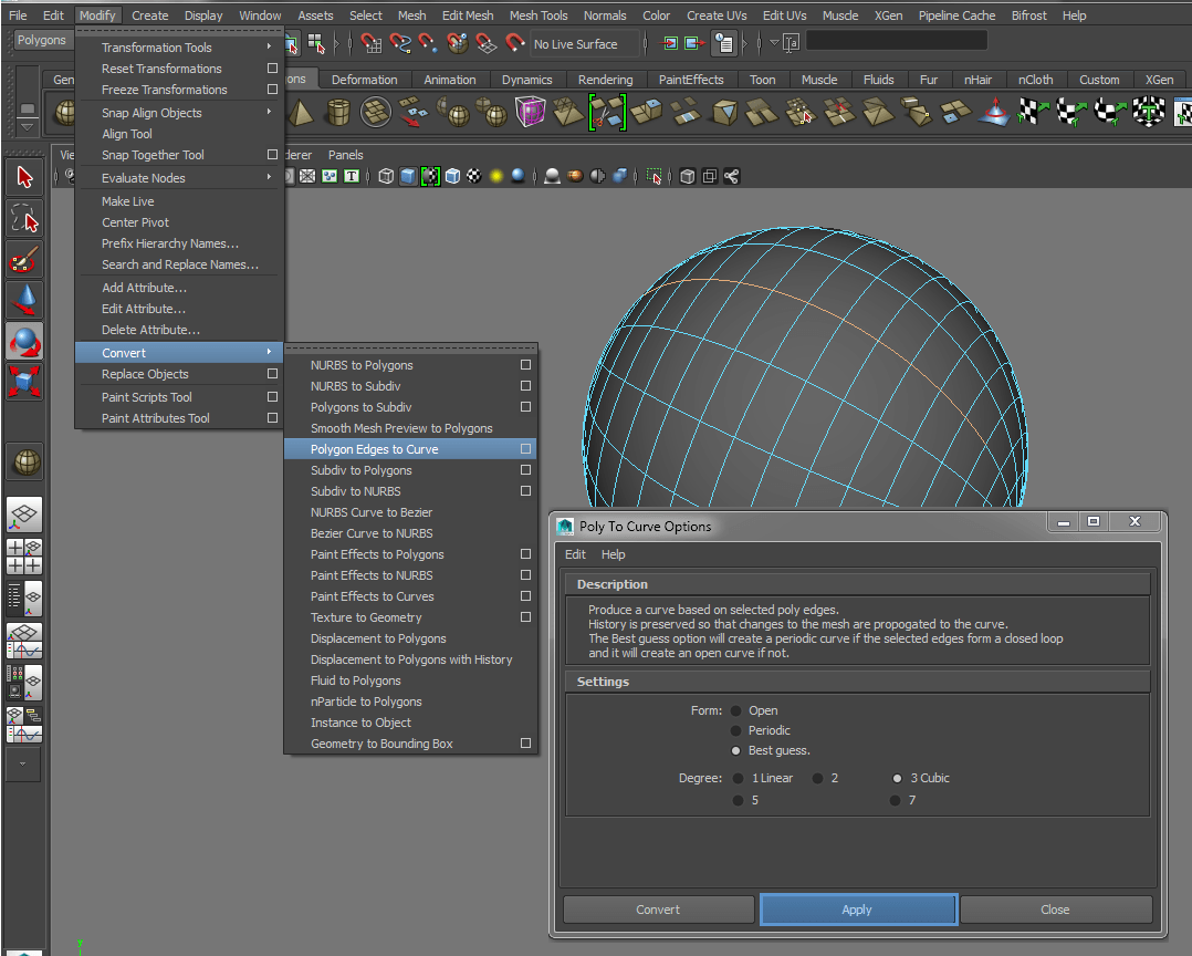
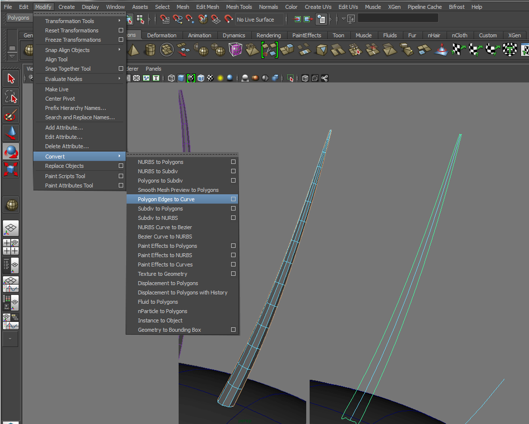
- 2.) Convert the Polygon edge to a Curve. Modify > Convert Polygon Edges to Curve.
- 3.) Apply the conversion. A new curve will be generated. Rename it to "Base Curve" or something easy to remember so you can find it later , if you need it.
- 4.) Select the curve and the geometry. Delete history and freeze transformations.
II. Creating the Top Edge Shape by drawing a curve along the surface.
Create the Top Edge Curve. The top edge curve will determine how tall the fin is as well as its general shape and flow. A good way to start building out the top edge of the fin is to draw out its flow while following the general curvature of the surface that will be built off of. The best way to do this to take advantage of "Live Surface" In Maya. When an object becomes a live surface. it acts as a virtual magnet. Any components you make will snap to the surface of your "Live Geometry".
1.) Make the source object "live". After selecting your object go to Modify > Make Live . You can also look for a magnet at the end of your "constraints " menu set. Your selected object will become a live surface when the button is selected. If you have wire-frame on, you'll notice the the wire-frame also turns green.

2.) Draw a curve on the surface. You can find various curve tools in the "Curves" Shelf or you can select one from the create Menu. Create > EP Curve tool or CV Curve tool. For this example , I used the EP curve tool but the CV curve tool also works fine.

3.) Turn off Live Surface and pull your new Fin Edge Curve upwards, to the approximate height you want the fin to be. Once you drag out the curve, refine the shape until you get a silhouette you like. To refine the shape of the curve, right click + drag to Control Vertex.
 |
| Tip: In your Move Tool, set the orientation to "Normals Average". The Vertices will move along the edge instead of through world space. |
III. Creating the overall shape by lofting the curves.
A "loft" creates a surface between two or more curves. In our case, the two curves that we want to create a surface between are our Base Curve and our fin edge curve. Lofting is a really easy process that allows us to create polygons directly from the menu.
- 1.) Select the curves you want to loft. For this tutorial. We want to loft a surface between Our Base Fin Curve and Our Top fin Curve.
- 2.) Switch to "Surfaces Menu Set" and the Select Surfaces > Loft>Option box.
- In the Surfaces Dialog : Parameterization : Uniform, Auto-Reverse : ON* | Surface Degree: Cubic * | Curve Range : Partial | Output Geometry : Polygons * | Type : Quads , Tessellation Method : Count | Count: 100 **
- * Auto-Reverse: Auto Reverse ON assumes that all of the curves are oriented the same way, so your surface wont twist and "implode" on itself
- * Cubic creates smoother results when lofting the surfaces. If you choose linear, surfaces may appear more faceted. If you are converting to Polygons, either method is fine because we can simply subdivide our mesh in the view-port to preview smoother surfaces.
- * Surface Degree: Cubic : Because we are using this as a reference surfaces, we can convert it directly into polygons. If you want to play with the shape more, you might have more control if you convert it to a NURBS surface. In the end, we want our fins to be polygons so this eliminates and extra conversion set.
- * Count 100 If the resolution is too low at 100 polygons, feel free to crank it up,.

At this point, we have a mesh that we can sculpt and refine with smaller details in Zbrush, but there are additional steps that can be taken to create spines and individual webbing.
B. Creating the Spines.
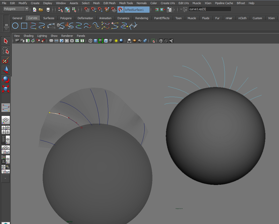
I. Creating the Guiding Curves by using the new Lofted Surface.
1.) Make your new Base Fin "Live". Select a curve tool and draw a few curves along the surface until you get something like this :
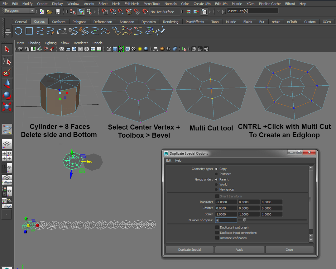
II. Creating the Spine Bases with a Cylinder Primitive.
- 1.) First create a cylinder with 8 sides. Delete the side and bottom faces. All you should have left are the top faces of the cylinder
- 2.) To make the new circle quad-friendly, select the center vertex and use the"Bevel" tool in the Modeling Tool Kit. This will create an octagon in the center of your shape. Use the multi cut tool to cut a cross through it. This will turn the center into four Quads.
- 3.) Add Resolution. With the Multi Cut tool still selected, Control + Click on an edge to create an additional edge-loop. This is an optional step that I perform in case I want to round out the points later during the sculpting phase.
- 4.) Duplicate the mesh so that you have as many cylinders as you have spine curves. In this case, I have eleven spine curves so I want eleven circles. I used Duplicate special to do this,
III. Positioning the Spine Bases using Align to Curve.
- 1.) Select all of the circle instances you have created and Shift + Select the base Curve that we created at the beginning of the tutorial.
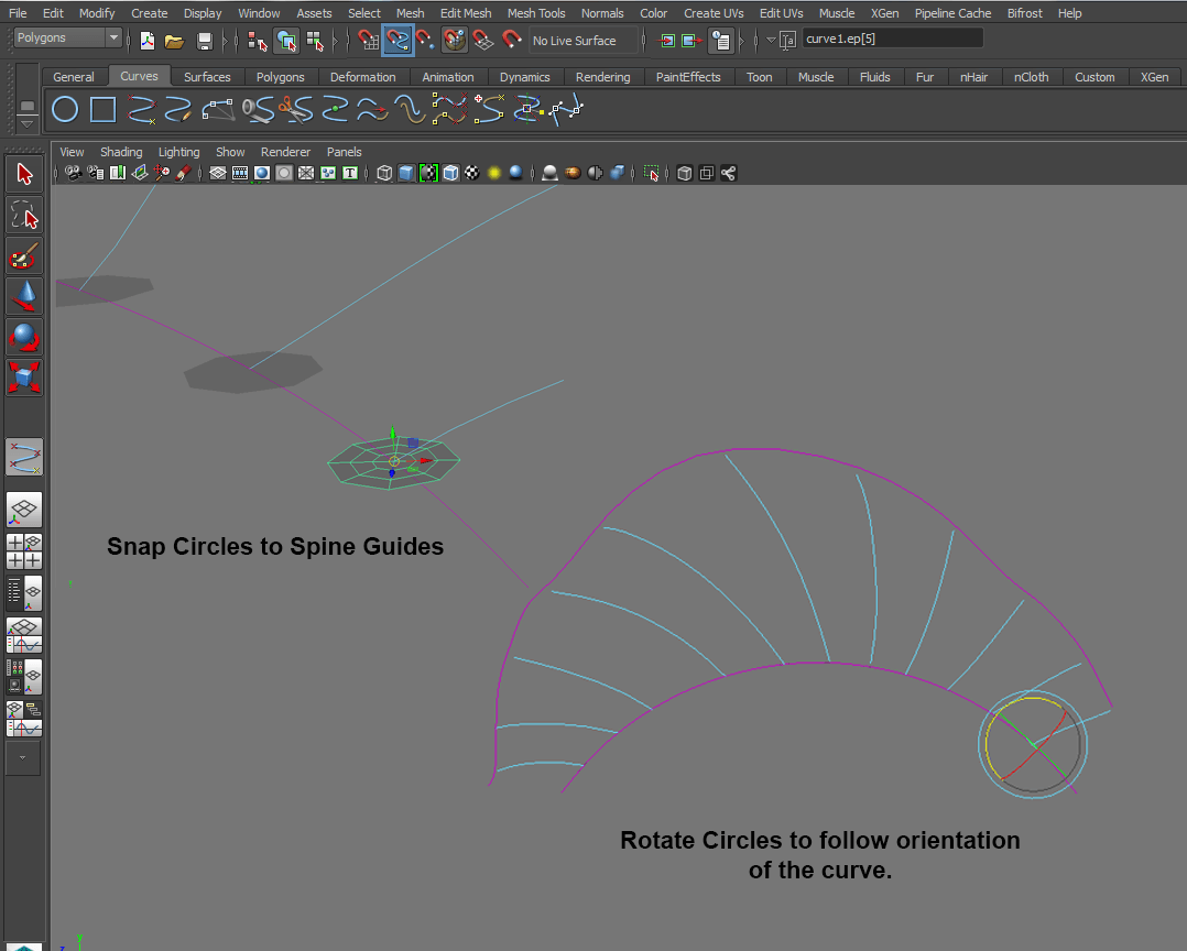
- 2.) Snap the Circles equally across the selected Curve . Modify > Snap Align Objects > Position Along Curve
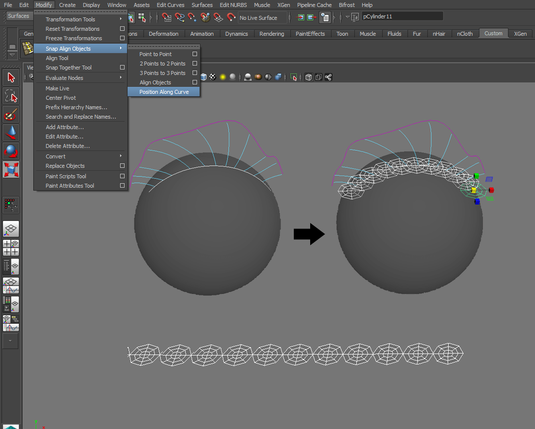
- 3.) The Circles will snap to the base curve and will be spaced evenly. The problem with this is that The Cylinders won't be lined up with the spine guides. Select the "Snap to Curve" Constraint in the Constraints panel, and begin moving the circles with the center control. Notice how they snap to the edge.
- 4.) Orient the Circles to the curves. Using the Rotate tool set to Object Base Rotation, Roughly orient each of the cylinders so that their faces point in the same general direction of the curve .
- *This step is optional. If you don't wish to orient your circles to the curve, simply drag them a little lower below your base mash, they will work just fine.
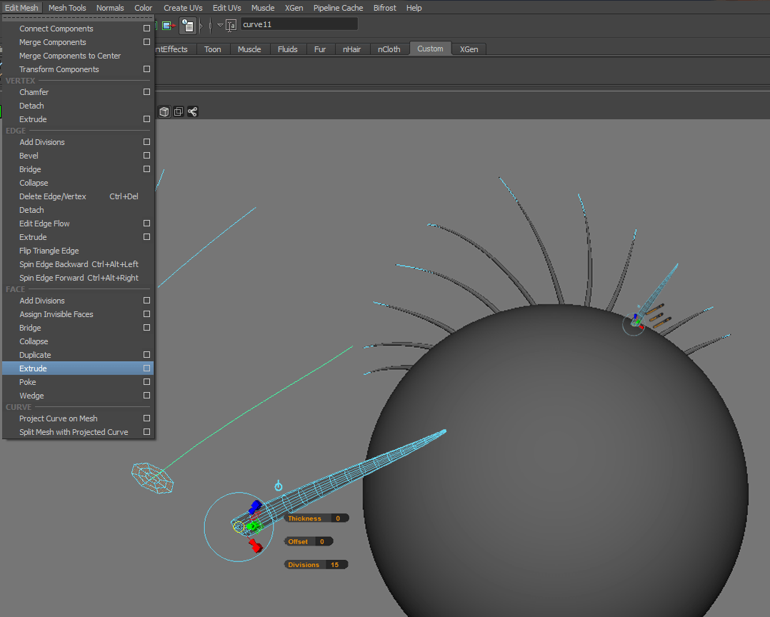
IV. Extruding Faces along a Curve to create the spines.
- 1.) First select the Geometry you want to extrude. Enter face mode and drag + select all the faces.
- 2.) With all the faces selected, Shift and select the curve you want the faces to follow.
- 3.) Extrude the faces along the curve. Edit Mesh > Extrude ( Under Faces) . Set the divisions to a number that creates a smooth transition along the curve. For the spines in this example, I set the divisions to 15. In the attribute editor, I played with the taper values until I found a value I liked ( 0.1)
- 4.) Repeat this process for all of the circles/spines.
A. Lofting Fin Shapes.
To create the fins, we need three curves. Two curves will determine the width of the fins ( The width should end between each spine) and the third curve should determine the shape of the webbing as it stretches between each spine. Fins come in a variety of shapes and sizes. For my personal project , my fins had a convex curve that extruded from approximately 5/6th the length of the spine and peaked above the ending tips. For this example, we will create "concave" curves, that curve inward between each fin, like sails.
Since we are using curves, we don't have to be stuck to one idea. After lofting, we can easily tweak the silhouette by moving the curves.
I. Creating the Side Edges of the Fins by Converting Edges to Curves..
- 1.) First , we need to insure that each segment of the fin begins and ends with each spine edge. To do this we are going to perform the same steps we did in Part A. I ( Making the base with Edges to Curves) . But instead of selecting a curve of our main geometry, we want to select the outer edges of each spine and extract curves from them. Find the outer edge> Double click + Select the edge. Modify > Convert > Polygon Edges to Curve.
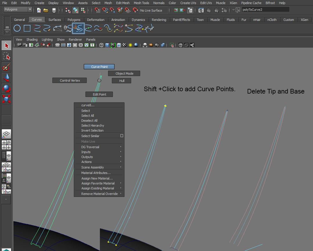
- 2.) Next, we need to isolate the sides of the extracted curve. To do this, we need to cut the curve in four places. With your curve selected Right Click + Drag and Select Curve Point. Click on the right corner of the base. Shift + Click On the left comer of the base to add another point. Repeat this for the tip of the curve. The points mark the areas that we want to cut the Curve at. Once all of your curve points are placed, Select the "Detach Curves" Icon under the Curves Shelf.
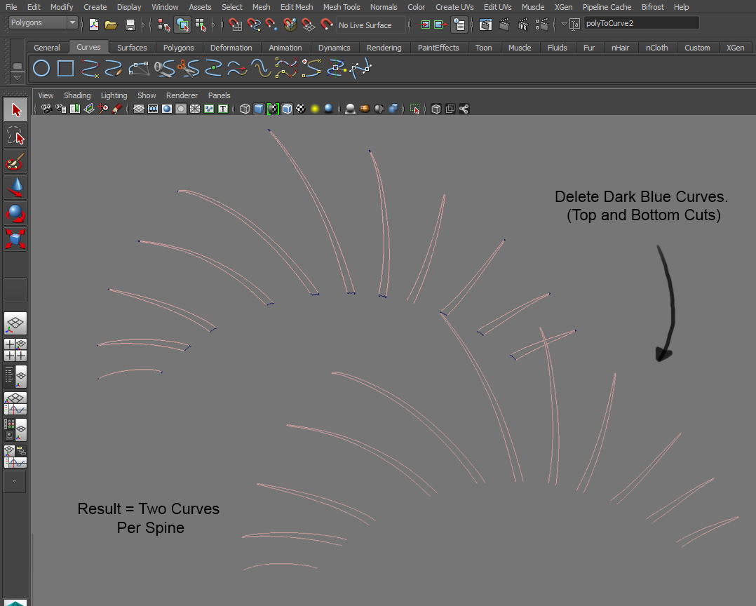
- 3.) Repeat these steps for all of your curves. In the end, you should have two curves per Spine, that follow the outer silhouette of the spines.
- 4.) For the first and last fin spine, we will only need the inner most curve to loft the fin. You can delete the outer edges.
II. Creating the Top Curve by Making the Base Fin Live.
- 1.) Un-hide the Base Fin Shape that was made in Part A. With the Base Fin Object Selected, Click the Magnet Icon in the Constraints section of the Menu header. Just like before, the live object will act as a magnet for the curves that we will build.
- 2.) With the Base Fin Shape live, select the EP Curve Tool and draw a curve between each Spine Curve. ( To save time, hold down C to snap to curve, while dragging your first and last points of the top curve so that it will snap to the spine or "rail" curves. )
- 3.) Once all the top Curves are created, the base Fin Shape is no longer needed. Turn off "Make live" and had the Base Fin Surface.

- 4.) Finally, we need to cut the curves so that the low end of the new Concave top-curve, meets end- to end with the side curves. To do this, select the curve you want to cut , right Click + Drag to Curve point. Click and create a point, and then "Detach Curve" with the Cut Icon in the Curves Shelf.

III. Preparing the Curves for Birail Lofting.
Working with Birail lofting is tricky to say the least, but there are a few things that we can check and prep in order to have a seamless and easy lofting experience with this tool. In order to get birail to work properly, it is best practice to check for the following :
- A.)Do the ends of our " profile curve" line up with the ends of our two side rails?
- B.)Do our side rails have the same amount of control points?
A.) Do the ends of our " profile curve" line up with the ends of our two side rails?
There are multiple ways to address this , but I found that the easiest and cleanest way, for me, was to "attatch" all of my curves" and then to cut them at each corner.
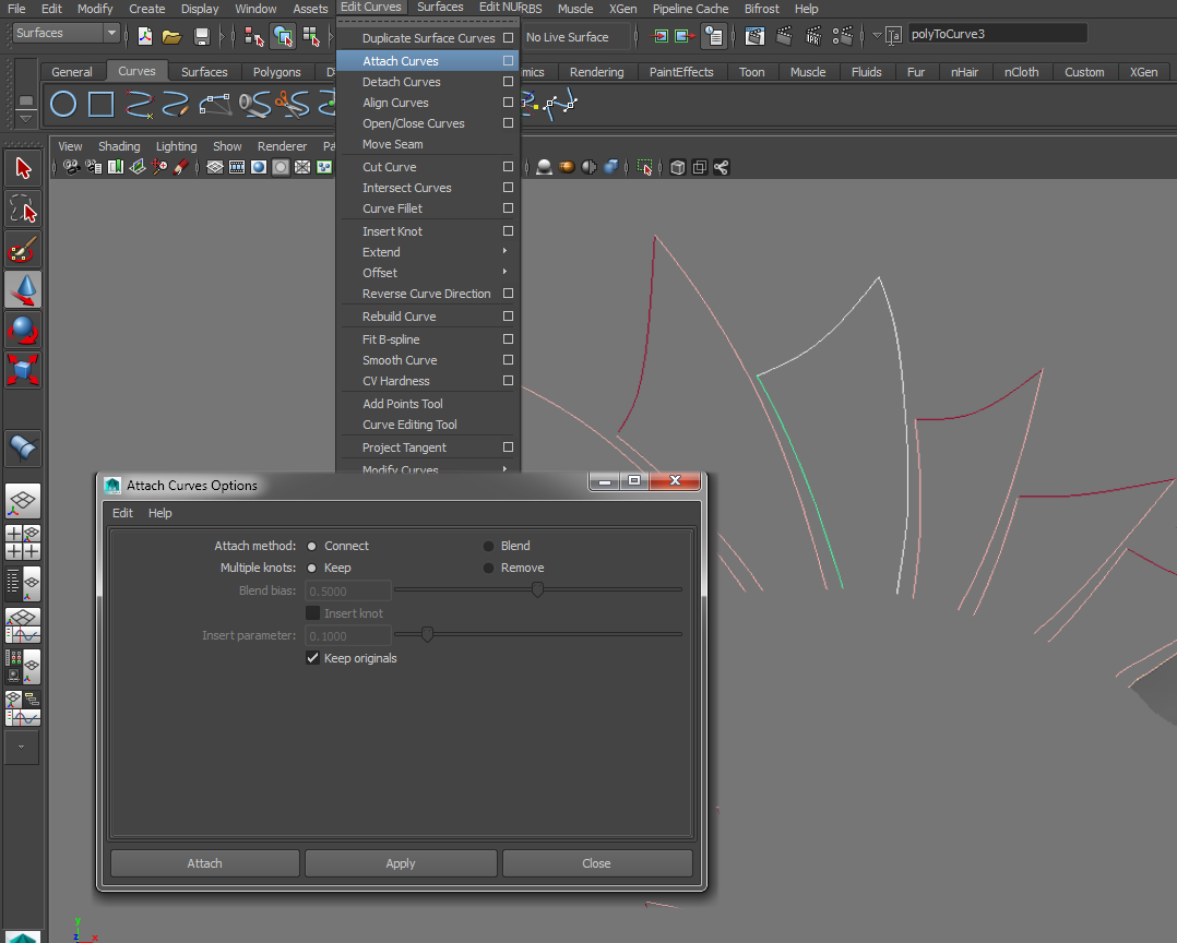
- 1. Select all three curves that define the silhouette of a single fin shape. In the "Surfaces" UI : Edit Curves > Attach Curves > Option Box || Attach Method : Connect | Multiple Knots : Keep | Hit apply.
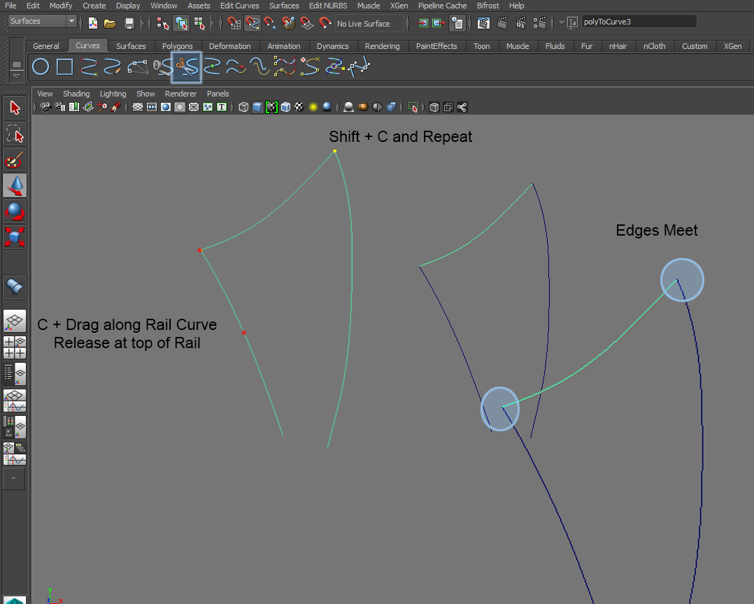
- 2. Right Click on your newly combined curve and select "Curve Point". Like we did in throughout this tutorial , we are going to cut the curves at the curve point using "Detach Curves" Icon.
- Hint : Hold down C to Snap the curve point along your rails. It will stop sliding at the corner. release, and Shift +C + Drag, on the other side of the fin silhouette.
- 3. Cut the Fin at the location of the new curve points. This will insure that our "profile curve" begins and ends exactly where the right and left rails begin.
B.) Do our side rails have the same amount of control points?
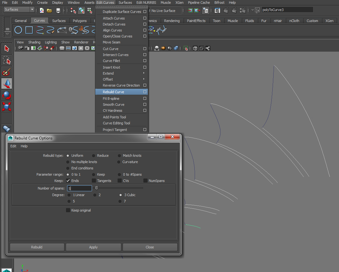
Most likely, the answer is "no" . In this case, we have to "rebuild" our curves so that they have the same amount of control points.- 1. Select the curves you want to rebuild. In the case of this tutorial, I want to rebuild all of my "rail" curves first.
- 2. In the Surfaces UI : Edit Curves > Rebuild Curve > Option Box . Rebuild Type : Uniform | Parameter Range : 0 to 1 | Keep : Ends | Number of Spans : 5 ** | Degree : 3 Cubic .Hit Apply to unify your selected curves.
- ** Choose a number that still keeps the general shape of your curve as close to the original as posible. If you want the curve to match the exact silhouette of the spine, give it as many spans as there are divisions along the spine ( these spines have 15 divisions. ) Its important to know that the higher the spans, the more likely that your surfaces could appear bumpy.
- 2.) Repeat this process with the "profile curve"
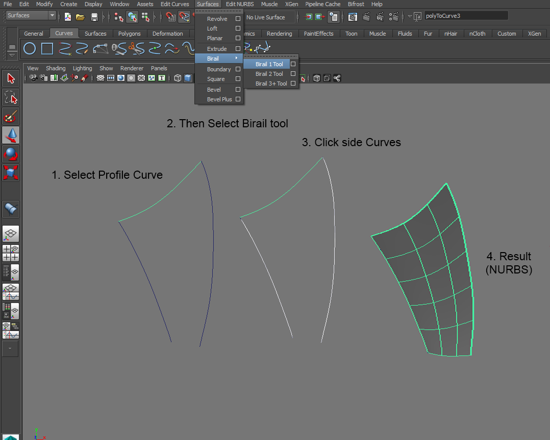
IV. Creating fin surfaces with Birail Loft 1.
The birail tool is really easy to use once all of the curves are cleaned up and prepped.
- 1.) To start the Birail loft, Select the concave curve ( profile curve).
- 2.) With the profile curve selected, Select Surfaces > Birail> Birail Loft 1.
- 3.) The Drop down menu will disappear and your most icon will become more angular. At this point , go ahead and click each of the "rail curves".
- 4.) If done, correctly, a surface will appear filling the shape between the three curves.
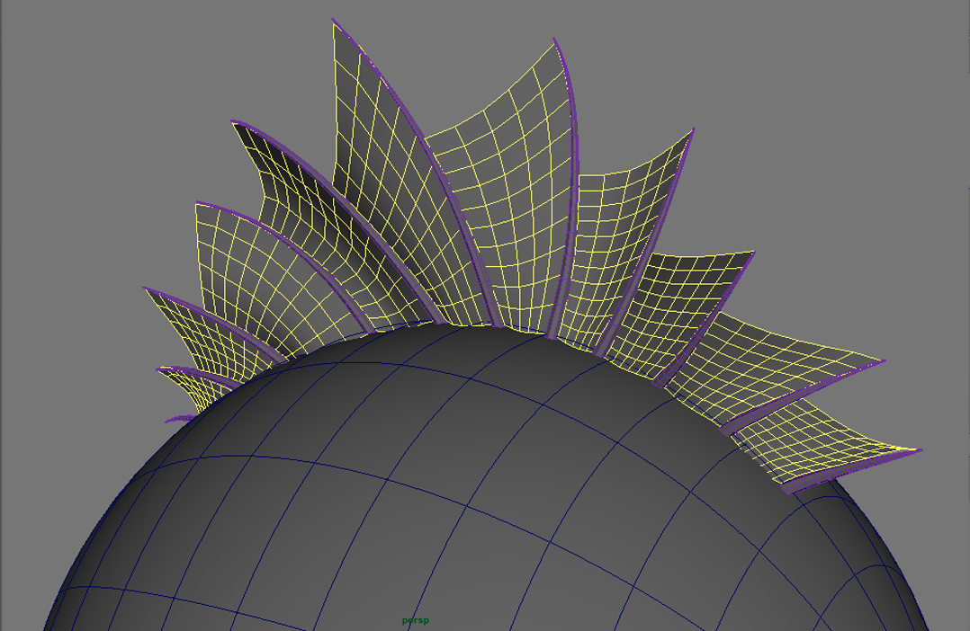
- 5.) Repeat the process for all of the rest of the fin silhouettes.
IV. Converting NURBS Surfaces to Polygons.
- 1.) Select the surface you want to convert
- 2.) Convert the surface to polygons. Modify > Convert > Nurbs to Polygons> Option Box Type : Quads , Tessellation Method : Count | Count: 100 **
- 3.)Repeat this step for all of your lofted surfaces. In the end, you should have polygon faces that can be rendered or exported to a sculpting program like Zbrush.
Comments
Post a Comment